The plan was to turn a really cheap Maplin (rip) robot, into something with a little bit more intelligence. The original robot as purchases for about £5, it had two little motors and a micro that would randomly tell it what to do, forward, left or right. We saw an oportunity here, effectivly a really cheap chassis to control. Even the voltage was right, 3 volts!
Rip out the origial PIC micro, and conect a Nime Computer PCP3L board to the motor drive inputs. Wire up power to the existing board and carefully secure the Nime Computer to the Maplin board with diligent use of sticky tape and packaging plastics.
The image below shows the initial result
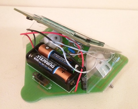
The rear view clearly shows the original battery back, which was well capable of running the motors and the Nime Computer board.
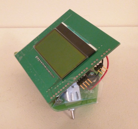
The view above shows how the Nime Computer has mounted to the original robot PCB.
At this stage it was possible to program the robot to follow a pre-determined pattern. Better than the randomness of before, but still not good enough. The next section takes it a little further.
The next stage was to create some proximity sensors, so that the robot cold react to obstables before actually hitting them. Infrared LED and phototransistor pairs were used along with the analogue ports on the Nime Computer to allow the robot to sense distance forward left and right.
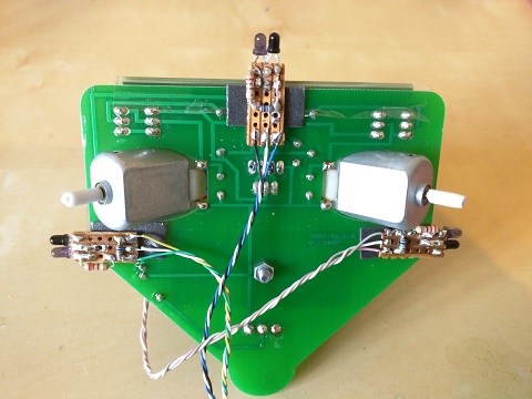
The image above shows the three sensors attached to the underside of the robot. Each IR LED was connected to a separate digital output on the PicoCreate so that only the sensor being read would be emitting light (battery saving).
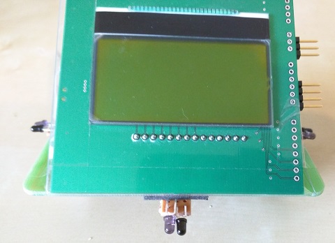
The final robot is shown above, the front view.
Well sort of. The proximity sensors only really had a useful range of about 4cm, so the robot couldn't be left to move very fast if it was going to react in time. Also, the motors had to be slowed-down, using a form of 'software PWM'
