This project demonstrates how to blink an LED, it's like the 'Hello World' of embedded projects.
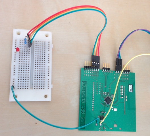
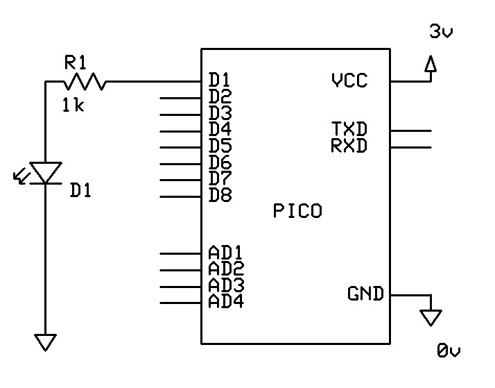
One of the digital input output pins is used to drive the LED directly. A current limiting resistor is must always be used with LEDs, so R1 in the diagram below serves this purpose.
The SYS 10 call on line 30 is used to configure D1 as an output. Line 50 uses the SYS 11 call to set the output of the D1 pin to 1 (which means output 3 volts). Line 60 waits for about half a second. On line 80, the SYS 11 call is used to set the D1 pin to 0 (which means turn it off, setting it to 0 volts)
Line 90 follows with another half second wait and line 100 jumps back to line 50 to repeat the process.
This program will continue to run until the escape key is pressed (or CTRL-Z send over the serial port).
10 REM ** BLINKY **
20 REM Setup pin 1 as an output
30 SYS 10,1,1
40 REM * Turn output on *
50 SYS 11,1,1
60 WAIT(500)
70 REM TURN output off *
80 SYS 11,1,0
90 WAIT(500)
100 GOTO 50